Tumbling Mill (Speed): Difference between revisions
md>Scott.Munro m (→Excel) |
Scott Munro (talk | contribs) m (1 revision imported) |
(No difference)
| |
Revision as of 05:21, 16 November 2022
Description
This article describes mathematical methods for converting between the rotational and fraction critical speeds of a tumbling mill.
The critical speed of a horizontal tumbling mill is defined as the minimum speed at which a single element (ball, rod, rock etc.) will remain in contact with the mill wall for a full rotation. The critical speed is therefore a function of mill diameter, rotational speed and the force of gravity.
Tumbling mill speed is frequently referred to as the fraction of critical speed the mill is operating at.
The fraction critical speed of a mill has particular relevance to the mathematical modelling of grinding product size, power draw, and other properties.
Model theory
The theoretical critical speed of a tumbling mill, [math]\displaystyle{ N_c }[/math] (rev/min), is defined as:[1]
- [math]\displaystyle{ N_c = \dfrac{60}{2 \pi} \sqrt \dfrac{2g}{D_m} }[/math]
where [math]\displaystyle{ D_m }[/math] is the mill diameter inside liners (m) and [math]\displaystyle{ g }[/math] is acceleration due to gravity (m/s2).
Therefore, the fraction critical speed, [math]\displaystyle{ \phi }[/math] (frac), given a rotational mill speed, [math]\displaystyle{ N_m }[/math] (rev/min), is computed as:
- [math]\displaystyle{ \phi = \dfrac{2 \pi N_m}{60}\sqrt{\dfrac{D_m}{2g}} }[/math]
and the rotational mill speed given a fraction critical speed is:
- [math]\displaystyle{ N_m = \dfrac{60 \phi}{2 \pi}\sqrt{\dfrac{2g}{D_m}} }[/math]
Excel
The fraction critical speed of a tumbling mill may be computed from the Excel formula bar with the following function call:
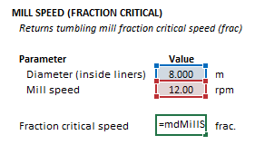
=mdMillSpeed_FracCS(millDiameter As Double, millRPM as Double)
The millDiameter, millRPM and function results are defined for the fraction critical speed function below in matrix notation, along with example images showing the selection of the same cells in the Excel interface:
[math]\displaystyle{ millDiameter = D_m\text{ (m)} }[/math]
[math]\displaystyle{ millRPM= N_m\text{ (rpm)} }[/math]
[math]\displaystyle{ mdMillSpeed\_FracCS = \phi\text{ (frac)} }[/math]
The rotational speed of a tumbling mill may be computed from the Excel formula bar with the following function call:
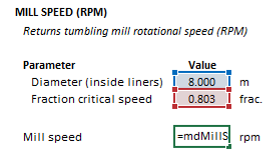
=mdMillSpeed_RPM(millDiameter As Double, fracCriticalSpeed as Double)
Invoking the function with no arguments will print Help text associated with the model, including a link to this page.
The millDiameter, fracCriticalSpeed and function results are defined for the fraction critical speed function below in matrix notation, along with example images showing the selection of the same cells in the Excel interface:
[math]\displaystyle{ millDiameter = D_m\text{ (m)} }[/math]
[math]\displaystyle{ fracCriticalSpeed = \phi\text{ (frac)} }[/math]
[math]\displaystyle{ mdMillSpeed\_RPM = N_m\text{ (rpm)} }[/math]
See also
- Ball Mill (Perfect Mixing)
- Ball Mill (Perfect Mixing, Dynamic)
- Ball Mill (Overfilling)
- Tumbling Mill (Media Trajectory)
- Tumbling Mill (Power, Hogg and Fuerstenau)
- Tumbling Mill (Power, Morrell Continuum)
- Tumbling Mill (Power, Morrell Empirical)
- Tumbling Mill (Power, Morrell Discrete Shell)
- Tumbling Mill (Power, Hilden and Powell)
- Tumbling Mill (Slurry Flow)
References
- ↑ King, R.P., 2012. Modeling and Simulation of Mineral Processing Systems. Elsevier.

