Pump (Centrifugal, Slurry)
Description
The article describes a method for estimating the performance of a centrifugal slurry pump.
Centrifugal pumps are a critical component of metallurgical processing plants. The transport of solid particles in slurries presents additional complexity, as pumps are typically tested and rated for water duties only.
The centrifugal slurry pump modelling approach described below has the following features:
- The reduction of typical vendor pump performance curves into generalised mathematical relationships for computational implementation
- The de-rating of water duty pump performance for heterogenous slurries
- Estimation of the effects of elevation, piping system properties and transport destination processing equipment (e.g. hydrocyclones)
- An estimation of the settling velocity of slurries during transport
Note that the centrifugal slurry pump model described here is not intended to replace the more comprehensive design methods and tools currently available. Rather, it is intended to provide the user with a comparatively simpler tool which can be integrated with other unit models and provide useful estimates of pump speed, flow rate, motor power, and pressure head in the broader context of a mineral processing circuit. More sophisticated methods should be applied for engineering design or optimisation.
Model theory
The centrifugal slurry pump modelling methodology outlined in this section applies to pump duties where:[3]
- The distance to be pumped is short (<200 m)
- The slurry is heterogenous (settling) and the mean particle size >50 μm
- The particle size distribution is not closely graded
- The height to elevate the slurry is within typical processing plant limits (e.g. <20 m)
- The pump is fed positively from a tank/hopper with the free surface of the slurry above the inlet level of the pump
- The transport medium is water between 0 and 60 °C
Generalised characteristic curves
The performance of a centrifugal pump is typically described by a set of characteristic curves relating pressure head, flow rate, pump speed and efficiency, as illustrated by the example in Figure 1.
King (2002) describes a method for generalising the multiple characteristic curves into a reduced functional form.[2]
Speed
King's procedure begins by specifying the pump head and flow rate in terms of two dimensionless groups, the pump head number, , and the pump flow number, ,:
where:
- is the total pressure head of the pump (m)
- is acceleration due to gravity (m/s2)
- is the pump rotation speed (revolutions per second, or Hz)
- is the pump impeller diameter (m)
- is the volumetric flow rate through the pump (m3/s)
The pump head number and pump flow number may then be linked by the following relation:
where , , and are the coefficients of the generalised speed characteristic curve function.
The coefficients of the above equation may be obtained from a set of characteristic curves (e.g. Figure 1) via regression, as demonstrated by the upper chart of Figure 2.
The performance of a specific pump under different operating conditions may then be estimated by application of the generalised speed characteristic curve with the determined coefficients.
The volumetric flow rate provided by a pump operating at a given speed and pressure head can be computed via the quadratic formula:
and .
Alternatively, the speed of a pump providing a given volumetric flow rate at a given pressure head may be computed by substituting the equations for and into the generalised characteristic speed equation and solving for :
Efficiency
Although not explicitly described by King, the efficiency characteristic curves are also amenable to the same generalisation procedure as the speed curves, i.e.:
where is the pump efficiency (kW/kW), and , , and are the coefficients of the generalised efficiency characteristic curve function.
As with the speed curves, regression techniques may be applied to extract the coefficients of the above equation, an example of which is shown in the lower part of Figure 2.
Total dynamic head
The total dynamic head is the equivalent pressure head that a pump acts against, taking into account static head, friction losses in the pipe, and pressure drops across connected equipment at the piping terminus, i.e.:
where:
- is the static head arising from elevation changes between the source and destination, including fluid head above the pump suction intake (e.g. a tank) (m)
- is the head caused by friction losses through the connected piping system (m)
- is the head due to pressure drops across equipment at the end of the piping system, such as hydrocyclones etc (m)
Friction losses may be estimated by the Darcy-Weisbach equation:[4]
where:
- is the friction factor
- is the equivalent pipe length, including the effect of fittings, valves, bends etc. (m)
- is the flow velocity in the pipe (m/s)
- is the inside pipe diameter (m)
and the pipe velocity is:
Total dynamic head is therefore related to pump flow rate via friction head:
- The flow rate of a pump operating at a given speed is itself a function of total dynamic head, creating a dependence between the two terms.
- The dependence is resolved via an iterative numerical solution.
- Iterative solution is not required when pump speed is being computed at a fixed feed flow rate.
Friction factor
Many methods exist to estimate the friction factor, , e.g. see here.
Two methods are implemented in this model, the Colebrook phenomenological equation and the Churchill approximation.
The Colebrook equation is:
where is the absolute surface roughness of the pipe interior (m), and is the Reynolds number:
where is the density of slurry (t/m3) and is the dynamic viscosity of the liquid (cP).
The Colebrook equation is valid for Reynolds numbers in excess of 4,000. Furthermore, the Colebrook equation requires solution by iterative numerical means due to appearing in both sides of the equation.
The Churchill approximation to Colebrook's formula is:
where
The Churchill approximation accounts for flow in the laminar regime, from Reynolds numbers above about 103, which is lower than the Colebrook equation.
Head ratio
Pump characteristic curves, such that illustrated in Figure 1., are almost exclusively derived from testing on pure water.
The performance of a pump is reduced by the presence of solids compared to the pure water case. Pump performance estimated by the characteristic curve methods above must therefore be de-rated from pure water to slurry conditions.
Centrifugal slurry pump derating is undertaken by approximating the head of water that is equivalent to the head of a particular slurry being pumped, via the equation:
where is the equivalent head of water (m) and is the head ratio (m/m) for the slurry.
The equivalent water head, , is then used in the characteristic curve equations above in place of the total head, .
The head ratio, can be estimated by many means. Two approaches are included in the centrifugal slurry pump model, the Cave and Warman approaches.
Cave method
The Cave equation is:[5]
where:
- is the concentration of solids in the slurry by weight (w/w)
- is the mean particle size diameter (μm), defined here as the 50% mass fraction passing size.
- is the Specific Gravity or density of solids (- or t/m3)
Warman method
Warman provides a nomograph method for approximating the head ratio of a pumped slurry.[6] The nomograph form is reproduced in Figure 3, including an example path through the approximation procedure. The property used by the nomograph is the concentration of solids by volume in the slurry (v/v).
The Warman nomograph has been digitised and an interpolative calculation procedure is integrated into the centrifugal slurry pump model as an option for estimating the head ratio.
Efficiency ratio
Similarly to the head ratio, the efficiency ratio (kW/kW) derates pump efficiency for slurry duty, i.e.:
where is the effective efficiency for the pump (kW/kW), accounting for slurry derating of the efficiency estimated from the characteristic curve.
The efficiency ratio is sometimes reported to be approximately equal to the head ratio. [5] Alternatively, the Warman nomograph provides a method for estimating the efficiency ratio based on the head ratio and volume fraction solids of the slurry (Figure 3, bottom right).
Motor Power
The power drawn by the pumping duty at the drive shaft, (kW), is:[2]
Due to electrical and mechanical inefficiencies, the power drawn by the motor, (kW), is:
where is the motor factor (kW/kW).
Froth Volume Factor
When determining pump performance, the volumetric flow rate of slurry may need to be adjusted for the presence of froth:[7]
where:
- is the Froth Volume Factor, the ratio of frothed slurry volume to the original (un-frothed) slurry volume (v/v)
- and are the volumetric flow rates of solids and liquids, respectively, in the slurry (m3/s)
Slurry density is similarly adjusted:
where (t/m3) is the density of the frothed slurry, used in place of in the pump performance equations when froth is present.
Settling velocity
The settling velocity of a heterogenous slurry can be estimated by using the Durand equation:[4]
where is the liquid density (t/m3), and is the dimensionless Durand factor which may be approximated by:[3]
The settling velocity may be compared to the actual pipe velocity to asses whether settling may be an issue for the application in question.
Pumps in series and parallel
Centrifugal pumps configured in series (stages) add the total head capability of each individual pump:
where is the number of stages in series and is pump head at stage (m).
If all the pumps are identical, then the head experienced by any pump is:
Pumps operating in parallel simply multiply the volumetric flow rate:
where is the number of pumps in parallel and is the volumetric flow rate provided by the pump at stage (m).
If all the pumps are identical, then the volumetric flow rate of any pump is:
Note that the assumption of identical performance for pumps within series or parallel configurations is a major simplification, which may not be strictly valid in practice due to differing piping system properties, pump wear, control configuration etc.
Excel
The centrifugal slurry pump model may be invoked from the Excel formula bar with the following function call:
=mdUnit_Pump_King(Parameters as Range)
Invoking the function with no arguments will print Help text associated with the model, including a link to this page.
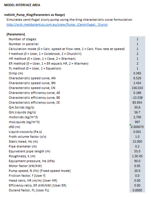
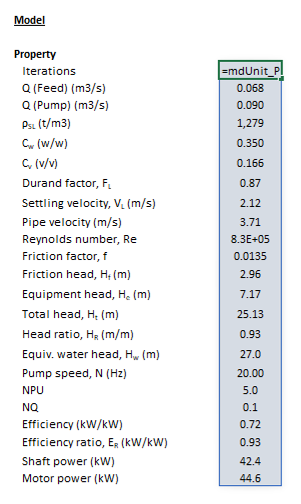
The Parameters array and model results are defined below in matrix notation, along with example images showing the same arrays in the Excel interface:
|
When calculating speed at flow rate ():
- and the value of is computed by the model and returned.
- This mode might be used to simulate the operating point of a variable speed pump in a steady state model, for example.
When calculating flow rate at speed ():
- is a user input and is computed and returned.
- The return value of may be different to .
- This might indicate a quantity of make-up water is required to maintain the level of a tank feeding the pump, for example.
SysCAD
The sections and variable names used in the SysCAD interface are described in detail in the following tables.
MD_Pump page
The first tab page in the access window will have this name.
Tag (Long/Short) | Input / Display | Description/Calculated Variables/Options |
---|---|---|
Tag | Display | This name tag may be modified with the change tag option. |
Condition | Display | OK if no errors/warnings, otherwise lists errors/warnings. |
ConditionCount | Display | The current number of errors/warnings. If condition is OK, returns 0. |
GeneralDescription / GenDesc | Display | This is an automatically generated description for the unit. If the user has entered text in the 'EqpDesc' field on the Info tab (see below), this will be displayed here.
If this field is blank, then SysCAD will display the unit class ID. |
Requirements | ||
On | CheckBox | This enables the unit. If this box is not checked, then no model calculations or actions are performed. |
Options | ||
ShowQIn | CheckBox | QIn and associated tab pages (eg Sp) will become visible, showing the properties of the combined feed stream. |
ShowQOut | CheckBox | QOut and associated tab pages (eg Sp) will become visible, showing the properties of the overflow stream. |
SizeForPassingFracCalc | Input | Size fraction for % Passing calculation. The size fraction input here will be shown in the Stream Summary section. |
FracForPassingSizeCalc | Input | Fraction passing for Size calculation. The fraction input here will be shown in the Stream Summary section. |
Stream Summary | ||
MassFlow / Qm | Display | The total mass flow in each stream. |
SolidMassFlow / SQm | Display | The Solids mass flow in each stream. |
LiquidMassFlow / LQm | Display | The Liquid mass flow in each stream. |
VolFlow / Qv | Display | The total Volume flow in each stream. |
Temperature / T | Display | The Temperature of each stream. |
Density / Rho | Display | The Density of each stream. |
SolidFrac / Sf | Display | The Solid Fraction in each stream. |
LiquidFrac / Lf | Display | The Liquid Fraction in each stream. |
Passing | Display | The mass fraction passing the user-specified size (in the field SizeForPassingFracCalc) in each stream. |
Passes | Display | The user-specified (in the field FracForPassesSizeCalc) fraction of material in each stream will pass this size fraction. |
Pump page
The Pump page is used to specify the input parameters for the centrifugal slurry pump model.
Tag (Long/Short) | Input / Display | Description/Calculated Variables/Options |
---|---|---|
Pump | ||
HelpLink | Opens a link to this page using the system default web browser. Note: Internet access is required. | |
Iterations | Display | Shows the number of internal model iterations (per SysCAD step) required to converge the pump model. |
Duty | ||
NumStages | Input | The number of sequential duplicate pump stages. |
NumParallel | Input | The number of duplicate pumps in parallel. |
Config | ||
CalculationMode | Speed | The model calculates the speed required to pump the volumetric flow rate of the feed stream, at the given head. |
Flow Rate | The model calculates the pump flow rate at the user-specified speed and head. | |
TransferPull | CheckBox |
|
CharacteristicCurve | ||
ImpellerDiameter / Dimp | Input | Diameter of the pump impeller. |
AN | Input | Coefficient of the generalised characteristic curve equation. |
BN | Input | Coefficient of the generalised characteristic curve equation. |
CN | Input | Coefficient of the generalised characteristic curve equation. |
EfficiencyCurve | ||
AE | Input | Coefficient of the generalised efficiency curve equation. |
BE | Input | Coefficient of the generalised efficiency curve equation. |
CE | Input | Coefficient of the generalised efficiency curve equation. |
Feed | ||
FrothVolumeFactor / FVF | Input | Value of the Froth Volume Factor. |
VolFlow / Qv | Display | Volumetric flow of solids and liquids in the pump feed stream, adjusted by the Froth Volume Factor. |
SolidDensity / SRho | Display | Density of solids in the pump feed stream. |
Liquids / LRho | Display | Density of liquids in the pump feed stream. |
SlurryDensity / SLRho | Display | Density of slurry (solids plus liquids) in the pump feed stream. |
SolidFrac / Sf | Display | Mass fraction of solids in the feed stream. |
SolidVolFrac / Svf | Display | Volume fraction of solids in the feed stream. |
LViscosity | Display | Viscosity of liquids in the feed stream. |
Userd50 | CheckBox | Indicates user-specified d50 value. Default is to use d50 computed from the feed stream. |
d50 | Input/Display | Mean size of particles in pump feed. |
Head | ||
StaticHead | ||
StaticHead / Hs | Input | Static head component of the total dynamic head. |
FrictionHead | ||
Method | User Defined | The friction factor is specified by the user. |
Colebrook | The Colebrook equation is used to estimate the friction factor. | |
Churchill | The Churchill equation is used to estimate the friction factor. | |
PipeDiameter / D | Input | Internal diameter of the pipe |
EquivPipeLength / L | Input | Equivalent length of the pipe, including pipe fittings etc. |
FrictionFactor / f | Input / Display | Friction factor used to estimate friction head. |
Roughness / k | Input | Absolute surface roughness of the pipe internal wall. |
ReynoldsNumber / Re | Display | Reynolds Number of the pipe flow stream. |
FrictionHead / Hf | Display | Friction head component of the total dynamic head. |
EquipmentHead | ||
EquipmentPressure / Pe | Input | Pressure drop due to equipment at the end of the pipe. |
EquipmentHead / He | Display | Pressure drop due to equipment at the end of the pipe, converted to head measurement units. |
Total head | ||
TotalHead / Ht | Display | Total dynamic head that the pump acts against. Sum of static, friction and equipment heads. |
HeadRatio | ||
Method | User Defined | The head ratio is specified by the user. |
Cave | Cave's method is used to estimate the head ratio. | |
Warman | The Warman method is used to estimate the head ratio. | |
HeadRatio / HR | Input / Display | Head ratio of the slurry stream. |
EquivWaterHead / Hw | Display | Head of water equivalent to the slurry total dynamic head, as estimated via the head ratio. |
EfficiencyRatio | ||
Method | User Defined | The efficiency ratio is specified by the user. |
Equals HR | The efficiency ratio is set equal to the value of the head ratio. | |
Warman | The Warman method is used to estimate the efficiency ratio. | |
EfficiencyRatio / ER | Input / Display | Efficiency ratio of the slurry stream. |
SettlingVelocity | ||
Method | User Defined | The Durand factor is specified by the user. |
Durand | The Durand factor is estimated by the Durand equation. | |
DurandFactor / FL | Input / Display | Durand factor to be used in the Durand equation. |
SettlingVelocity / VL | Display | Settling velocity estimated by the Durand equation. |
PipeVelocity / V | Display | Velocity of flow through the pipe at pump flow rate, Q. |
Speed | ||
N | Input / Display | Rotational speed of the pump. |
Q | Display | Volumetric flow rate of the pump at the given speed and head. |
HeadNumber / NPU | Display | Dimensionless pump head number used in calculations. |
FlowNumber / NQ | Display | Dimensionless pump flow number used in calculations. |
Power | ||
MotorFactor / Eta | Input | Efficiency factor of the pump. Fraction of power input to the motor which is useable by the pump at the shaft to move fluid. |
Efficiency / E | Display | Efficiency of the pump. |
ShaftPower / PShaft | Display | Power drawn by the pump at the shaft. |
MotorPower / PMotor | Display | Power drawn by the pump motor, including inefficiencies. |
About page
This page is provides product and licensing information about the Met Dynamics Models SysCAD Add-On.
Tag (Long/Short) | Input / Display | Description/Calculated Variables/Options |
---|---|---|
About | ||
HelpLink | Opens a link to the Installation and Licensing page using the system default web browser. Note: Internet access is required. | |
Information | Copies Product and License information to the Windows clipboard. | |
Product | ||
Name | Display | Met Dynamics software product name |
Version | Display | Met Dynamics software product version number. |
BuildDate | Display | Build date and time of the Met Dynamics Models SysCAD Add-On. |
License | ||
File | This is used to locate a Met Dynamics software license file. | |
Location | Display | Type of Met Dynamics software license or file name and path of license file. |
SiteCode | Display | Unique machine identifier for license authorisation. |
ReqdAuth | Display | Authorisation level required, MD-SysCAD Full or MD-SysCAD Runtime. |
Status | Display | License status, LICENSE_OK indicates a valid license, other messages report licensing errors. |
IssuedTo | Display | Only visible if Met Dynamics license file is used. Name of organisation/seat the license is authorised to. |
ExpiryDate | Display | Only visible if Met Dynamics license file is used. License expiry date. |
DaysLeft | Display | Only visible if Met Dynamics license file is used. Days left before the license expires. |
References
- ↑ Weir Slurry Group, Inc, 2009. Slurry Pump Handbook - 2009. Fifth Edition, Electronic Version, February 2009.
- ↑ 2.0 2.1 2.2 King, R.P., 2002. Introduction to Practical Fluid Flow. Elsevier.
- ↑ 3.0 3.1 Griffiths, T. 2003. Slurry Pumping. Available at: https://www.ausimm.com/globalassets/insights-and-resources/minerals-processing-toolbox/slurryp0503.pdf (Accessed 7/1/2023).
- ↑ 4.0 4.1 Dunne, R.C., Kawatra, S.K., and Young, C.A. (eds), 2019. SME mineral processing and extractive metallurgy handbook. Society for Mining, Metallurgy & Exploration.
- ↑ 5.0 5.1 Engin, T. and Gur, M., 2003. Comparative evaluation of some existing correlations to predict head degradation of centrifugal slurry pumps. J. Fluids Eng., 125(1), pp.149-157.
- ↑ 6.0 6.1 Grzina, A., Roudnev, A. and Burgess, K.E., 2002. Slurry Pumping Manual. Warman International Ltd.
- ↑ Weir Minerals Division, 2009. Pumping froth. Technical bulletin no. 28, Aug. 2009.