Ball Mill (Overfilling): Difference between revisions
md>Scott.Munro m (Text replacement - "N_{eq}" to "N_{\rm eq}") |
imported>Scott.Munro mNo edit summary |
||
| (3 intermediate revisions by 2 users not shown) | |||
| Line 1: | Line 1: | ||
== Description == | == Description == | ||
This article describes several methods for estimating the maximum volumetric flow capacity of an '''''overflow ball mill''''', including the '''Shi''' (2016) and '''Arbiter''' ( | This article describes several methods for estimating the maximum volumetric flow capacity of an '''''overflow ball mill''''', including the '''Shi''' (2016) and '''Arbiter''' (1991) approaches.{{Shi (2016)}}{{Arbiter (1991)}} | ||
== Model theory == | == Model theory == | ||
{{Restricted content}} | |||
<hide> | |||
=== Shi method === | === Shi method === | ||
[[File:BallMillOverfilling1.png|thumb|450px|Figure 1. Overflow discharge tumbling mill profile showing Shi's assumed charge and slurry pool areas.]] | [[File:BallMillOverfilling1.png|thumb|450px|Figure 1. Overflow discharge tumbling mill profile showing Shi's assumed charge and slurry pool areas.]] | ||
Shi estimated the residence time of an overflow ball mill by considering the volume of slurry present in the grinding media interstices and slurry pool. | Shi (2016) estimated the residence time of an overflow ball mill by considering the volume of slurry present in the grinding media interstices and slurry pool. | ||
This was accomplished by adopting Morrell's (1996) simplified charge geometry and calculating the volume of slurry resident in each of the areas A-C in Figure 1:{{Morrell (1996a)}} | This was accomplished by adopting Morrell's (1996) simplified charge geometry and calculating the volume of slurry resident in each of the areas A-C in Figure 1:{{Morrell (1996a)}} | ||
| Line 24: | Line 27: | ||
The simplified charge geometry is defined by three parameters: | The simplified charge geometry is defined by three parameters: | ||
* the angular position of the ''toe'' of the charge, <math>\theta_{\rm t}</math> (rad) | * the angular position of the ''toe'' of the charge, <math>\theta_{\rm t}</math> (rad), | ||
* the angular position of the ''shoulder'' charge, <math>\theta_{\rm s}</math> (rad) | * the angular position of the ''shoulder'' charge, <math>\theta_{\rm s}</math> (rad), and | ||
* the radius of the ''inner charge surface'', <math>R_i</math> (m) | * the radius of the ''inner charge surface'', <math>R_i</math> (m). | ||
Morrell's equations are used to define the charge position, i.e.{{Morrell (1996a)}} | Morrell's equations are used to define the charge position, i.e.{{Morrell (1996a)}} | ||
| Line 36: | Line 39: | ||
where: | where: | ||
* <math>J_{t}</math> is the volumetric fraction of the mill occupied by balls and coarse rock (including void space and interstitial slurry) (v/v) | * <math>J_{t}</math> is the volumetric fraction of the mill occupied by balls and coarse rock (including void space and interstitial slurry) (v/v) | ||
* <math>\phi</math> (frac) is the theoretical [[Tumbling Mill (Speed)|fraction critical speed]] | * <math>\phi</math> (frac) is the theoretical [[Tumbling Mill (Speed)|fraction critical speed]]. | ||
The fraction of critical speed at which centrifuging actually occurs, <math>\phi_{\rm c}</math> (frac), is: | The fraction of critical speed at which centrifuging actually occurs, <math>\phi_{\rm c}</math> (frac), is: | ||
| Line 55: | Line 58: | ||
:<math>R_i = r_{\rm m} \left ( 1 - \frac{2 \pi \beta J_{\rm t}}{2 \pi + \theta_{\rm s} - \theta_{\rm t}} \right )^{0.5}</math> | :<math>R_i = r_{\rm m} \left ( 1 - \frac{2 \pi \beta J_{\rm t}}{2 \pi + \theta_{\rm s} - \theta_{\rm t}} \right )^{0.5}</math> | ||
where the fraction of total charge in the active region, <math>\beta</math> (frac), is: | where <math>r_{\rm m}</math> is the radius of the mill (m), and the fraction of total charge in the active region, <math>\beta</math> (frac), is: | ||
:<math>\beta = \frac{t_{\rm c}}{t_{\rm f} + t_{\rm c}}</math> | :<math>\beta = \frac{t_{\rm c}}{t_{\rm f} + t_{\rm c}}</math> | ||
| Line 65: | Line 68: | ||
where the mean rotational rate, <math>\bar N</math> (rev/s), is: | where the mean rotational rate, <math>\bar N</math> (rev/s), is: | ||
:<math>\bar N \approx \frac{N_{\rm m}}{2}</math> | :<math>\bar N \approx \frac{N_{\rm m}}{2}</math> | ||
and <math>N_{\rm m}</math> is the rotational rate of the mill shell (rev/s). | |||
The time taken to travel between the shoulder and toe of the charge in free flight during one revolution, <math>t_{\rm f}</math> (s), is: | The time taken to travel between the shoulder and toe of the charge in free flight during one revolution, <math>t_{\rm f}</math> (s), is: | ||
| Line 72: | Line 77: | ||
where the mean radial position <math>\bar r</math> (m), is: | where the mean radial position <math>\bar r</math> (m), is: | ||
:<math>\bar r = \frac{r_{\rm m}}{2} \left [ 1 + \left ( 1 - \frac{2 \pi J_{\rm t}}{2 \pi + \theta_{\rm s} - \theta_{\rm t}} \right )^{0.5} \right ]</math> | :<math>\bar r = \frac{r_{\rm m}}{2} \left [ 1 + \left ( 1 - \frac{2 \pi J_{\rm t}}{2 \pi + \theta_{\rm s} - \theta_{\rm t}} \right )^{0.5} \right ]</math> | ||
| Line 91: | Line 97: | ||
where <math>V_{\rm m}</math> is the volume of the mill (m<sup>3</sup>) and <math>R_{\rm m}</math> is the radius of the mill (m). | where <math>V_{\rm m}</math> is the volume of the mill (m<sup>3</sup>) and <math>R_{\rm m}</math> is the radius of the mill (m). | ||
The volume of the mill is calculated as the sum of a cylinder and two right | The volume of the mill is calculated as the sum of a cylinder and two right circular frustums:{{Gupta and Yan (2016)}} | ||
:<math>V_{\rm m} = \pi {R_{\rm m}}^2L + 2 \cdot \bigg[ \dfrac{\pi}{3} (R_{\rm m} - R_{\rm t}) \cdot \tan \alpha_{\rm c} \cdot \left ( {R_{\rm m}}^{2} + R_{\rm m} R_{\rm t} + {R_{\rm t}}^{2} \right) \bigg]</math> | :<math>V_{\rm m} = \pi {R_{\rm m}}^2L + 2 \cdot \bigg[ \dfrac{\pi}{3} (R_{\rm m} - R_{\rm t}) \cdot \tan \alpha_{\rm c} \cdot \left ( {R_{\rm m}}^{2} + R_{\rm m} R_{\rm t} + {R_{\rm t}}^{2} \right) \bigg]</math> | ||
where: | |||
* <math>L</math> is the length of the cylindrical (belly) section of the mill (m) | * <math>L</math> is the length of the cylindrical (belly) section of the mill (m) | ||
* <math>R_{\rm t}</math> is the radius of the discharge trunnion (m) | * <math>R_{\rm t}</math> is the radius of the discharge trunnion (m) | ||
| Line 167: | Line 173: | ||
=== Arbiter method === | === Arbiter method === | ||
Arbiter | Based on an analysis of industrial ball mills at five operations, Arbiter (1991) postulated that the axial velocity of pulp through a mill should be less than 2.2% of the mill's tangential velocity. The ''Arbiter Flow Number'', <math>N_{\rm q}</math>, is defined as the ratio of axial to tangential velocity and is determined from: | ||
:<math>N_{\rm q} = \dfrac{\left (\dfrac{Q}{\frac{\pi {D_{\rm m}}^2}{4} (0.5 - 0.66 J_{\rm t})}\right )}{\pi N_{\rm m} D_{\rm m}}, \quad N_{\rm q} < 0.0217</math> | |||
:<math> | where: | ||
* <math>Q</math> is the volumetric discharge rate of pulp from the mill (m3/s) | |||
* <math>D_{\rm m}</math> is the mill diameter (m) | |||
* <math>J_{\rm t}</math> is the volumetric charge fraction in the mill (v/v) | |||
* <math>N_{\rm m}</math> is mill rotational speed (rev/min) | |||
The Arbiter Flow Number equation may be rearranged to yield the following relation for the maximum volumetric discharge rate of slurry from a mill prior to overloading, <math>Q_{N_{\rm q}}</math> (m<sup>3</sup>/h): | |||
:<math>Q_{N_{\rm q}} = 0.0217 \dfrac{\pi^2}{4} {D_{\rm m}}^3 N_{\rm m} (0.5 - 0.66 J_{\rm t}) \cdot 3600</math> | |||
Overfilling may be a risk if the actual volumetric flow rate from the mill approaches or exceeds | Overfilling may be a risk if the actual volumetric flow rate to/from the mill approaches or exceeds <math>Q_{N_{\rm q}}</math>. | ||
== Additional notes == | == Additional notes == | ||
| Line 196: | Line 199: | ||
Arbiter's relations were developed from a limited database of five mills, the largest of which was 5.3 m diameter x 6.4 m length. | Arbiter's relations were developed from a limited database of five mills, the largest of which was 5.3 m diameter x 6.4 m length. | ||
</hide> | |||
== Excel == | == Excel == | ||
| Line 243: | Line 247: | ||
The Arbiter overflow discharge ball mill overfilling model may be invoked from the Excel formula bar with the following function call: | The Arbiter overflow discharge ball mill overfilling model may be invoked from the Excel formula bar with the following function call: | ||
<syntaxhighlight lang="vb">=mdMillOverfilling_Arbiter | <syntaxhighlight lang="vb">=mdMillOverfilling_Arbiter(Parameters as Range)</syntaxhighlight> | ||
{{Excel (Text, Help, No Arguments)}} | {{Excel (Text, Help, No Arguments)}} | ||
| Line 262: | Line 266: | ||
\begin{bmatrix} | \begin{bmatrix} | ||
Q_{N_{\rm q}}\text{ (m}^{3}\text{/h)}\\ | Q_{N_{\rm q}}\text{ (m}^{3}\text{/h)}\\ | ||
\end{bmatrix}\;\;\;\;\;\; | \end{bmatrix}\;\;\;\;\;\; | ||
</math> | </math> | ||
| Line 368: | Line 371: | ||
|style="background: #eaecf0" | Display | |style="background: #eaecf0" | Display | ||
|Estimated volumetric flow rate of slurry (solids + liquids) at Arbiters critical flow number limit. | |Estimated volumetric flow rate of slurry (solids + liquids) at Arbiters critical flow number limit. | ||
|} | |} | ||
Latest revision as of 11:21, 4 December 2024
Description
This article describes several methods for estimating the maximum volumetric flow capacity of an overflow ball mill, including the Shi (2016) and Arbiter (1991) approaches.[1][2]
Model theory
Excel
Shi method
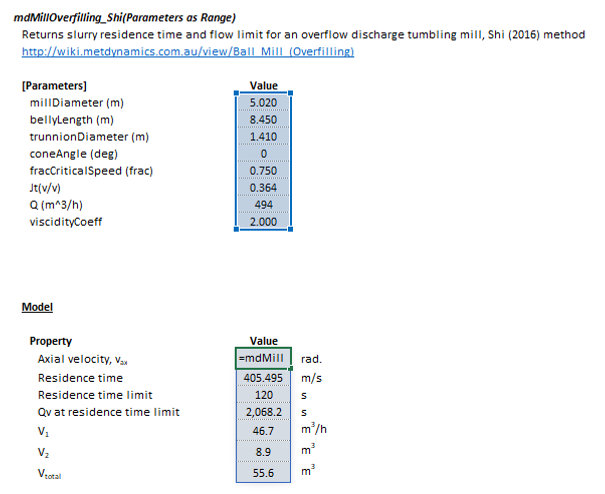
The Shi overflow discharge ball mill overfilling model may be invoked from the Excel formula bar with the following function call:
=mdMillOverfilling_Shi(Parameters as Range)
Invoking the function with no arguments will print Help text associated with the model, including a link to this page.
The Parameters array and model results are defined below in matrix notation, along with an example image showing the selection of the same arrays in the Excel interface:
|
|
Arbiter method
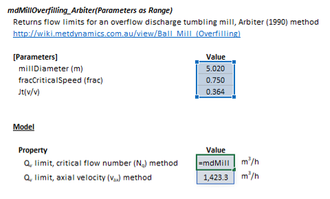
The Arbiter overflow discharge ball mill overfilling model may be invoked from the Excel formula bar with the following function call:
=mdMillOverfilling_Arbiter(Parameters as Range)
Invoking the function with no arguments will print Help text associated with the model, including a link to this page.
The Parameters array and model results are defined below in matrix notation, along with an example image showing the selection of the same arrays in the Excel interface:
|
|
SysCAD
The Ball Mill Overfilling Indicator model is an optional calculation for tumbling mill units. If selected, the input and display parameters below are shown.


