Tumbling Mill (Media Trajectory)
Description
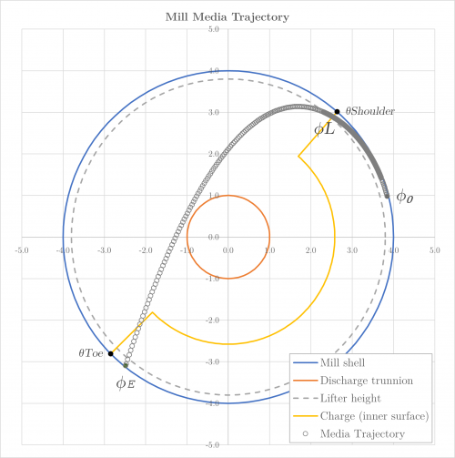
This article describes Powell's (1991) method for predicting the trajectory of the outer media elements in a tumbling mill.[1]
The approach predicts the point of impact of media elements projected into free flight after transit down a lifter bar surface, based on element size, lifter bar geometry, mill diameter and mill rotational speed.
The tumbling mill media trajectory model is particularly useful when combined with an estimate of charge position (e.g. Morrell's method), which allows analyses such as:
- Identifying and mitigating the risks of shell liner damage from media impact through lifter bar (or mill) design
- Monitoring trajectory and point of impact changes with charge level, mill speed or liner and lifter bar wear in operational mills
- Limiting the maximum operating speed (and hence power and throughput) in a mill simulation or process control sub-systems
Model theory
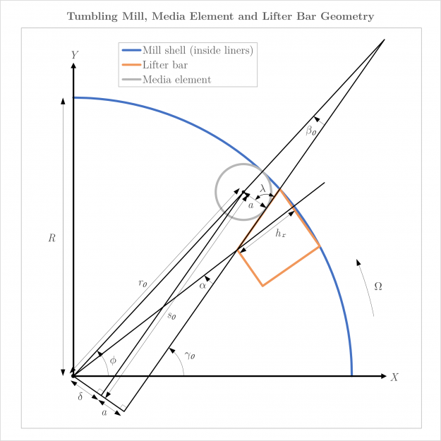
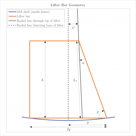
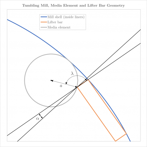
Powell's (1991) theory derives equations of motion for the outer media elements in a rotating tumbling mill based on a consideration of the acting gravitational, centrifugal and frictional forces.[1]
Outer elements are those that are initially in contact with both a lifter bar and the mill shell. The equations of motion are valid for both rod- or ball-type media elements, with minor formulation differences as outlined below.
The equations of motion are formulated based on the following sequence of events:
- A media element initially in contact with a lifter bar and the mill shell at the toe of the charge will eventually rise above the horizontal level as the mill rotates.
- A point of equilibrium is reached when the sum of the forces acting on the element is zero.
- At this stage, the media element begins to move down the face of the lifter bar via the mechanisms of rolling, sliding or a combination of the two, whilst the lifter continues to rise during mill rotation
- Once the media element reaches the tip of the lifter bar face, it is projected into free flight and travels under the influence of gravity until it again impacts the mill shell (or charge).
The equations of motion for each state are summarised below, with reference to the diagrams in Figures 2 and 3. Derivation of the equations is excluded from the summary.
Point of equilibrium
At the point of equilibrium, the sum of downward gravitational force, outward radial centrifugal force, normal force of the lifter bar, and frictional force between the lifter surface and the media element is zero.
The position of the point of equilibrium is defined by the angular displacement, [math]\displaystyle{ \gamma_0 }[/math] (rad), and distance along the lifter bar face, [math]\displaystyle{ s_0 }[/math] (m), of the media element centre.
The value of [math]\displaystyle{ \gamma_0 }[/math], the angle between the lifter bar face and the horizontal axis, is:
- [math]\displaystyle{ \gamma_0 = \begin{cases} \kappa + \arcsin \left ( \dfrac{\Omega^2}{g} r_0 \cdot \cos (\beta_0 - \kappa) \right ) & \lambda = \dfrac{\pi}{2}\\ \kappa - \lambda + \arccos \left ( - \dfrac{\Omega^2}{g} r_0 \cdot \sin (\lambda + \beta_0 - \kappa) \right ) & \lambda \gt \dfrac{\pi}{2}\\ \end{cases} }[/math]
where:
- [math]\displaystyle{ \kappa }[/math] is the friction angle, related to the coefficient of static friction between the lifter bar and the media element, [math]\displaystyle{ \mu_s }[/math], by [math]\displaystyle{ \mu_s = \tan \kappa }[/math]. If the effects of static friction are ignored, [math]\displaystyle{ \mu_s = 0 \implies \kappa = 0 }[/math].
- [math]\displaystyle{ \Omega }[/math] is the angular velocity of the mill (rad/s)
- [math]\displaystyle{ g }[/math] is acceleration due to gravity (m/s2)
- [math]\displaystyle{ r_0 }[/math] is the radial distance from the centre of the mill to the centre of the media element (m), i.e. [math]\displaystyle{ r_0 = R - a }[/math]
- [math]\displaystyle{ R }[/math] is the radius of the mill inside the liners (m)
- [math]\displaystyle{ a }[/math] is the radius of the media element (m)
- [math]\displaystyle{ \beta_0 }[/math] is the angle between the radial line passing through the centre of the outer media element and the lifter bar face (rad)
- [math]\displaystyle{ \lambda }[/math] is the angle between the lifter bar face and the radial line from the centre of the media element to the contact point with the lifter bar face (rad)
The value of [math]\displaystyle{ \beta_0 }[/math] is computed as:
- [math]\displaystyle{ \beta_0 = \arcsin \left( \frac{\delta}{r_0} \right ) }[/math]
where the distance [math]\displaystyle{ \delta }[/math] (m) is:
- [math]\displaystyle{ \delta = (R - h_r) \cdot \sin \alpha - a }[/math]
and [math]\displaystyle{ h_r }[/math] is the radial height of the lifter bar (m) and [math]\displaystyle{ \alpha }[/math] is the angle between the lifter bar face and a radial line from the centre of the mill through the tip of the lifter bar (rad).
The angle [math]\displaystyle{ \alpha }[/math] is related to the lifter bar geometry by the following equations:[2]
- [math]\displaystyle{ \alpha = \frac{\pi}{2} - \rho - \psi }[/math]
- [math]\displaystyle{ \psi = \begin{cases} \arctan \left ( \dfrac{y}{\left ( \sqrt{R^2 - y^2} - h \right ) } \right ) & \text{if }\rho = \frac{\pi}{2}, \text{ i.e. }90^{\circ}\\ \arctan \left ( \dfrac{y. \tan \rho - h}{\left ( \sqrt{R^2 - y^2} - h \right ) \tan \rho } \right ) & \text{otherwise}\\ \end{cases} }[/math]
where:
- [math]\displaystyle{ \rho }[/math] is the angle between the face surface and the base of the lifter bar (rad)
- [math]\displaystyle{ \psi }[/math] is the angle between the radial line bisecting the base of the lifter and the radial line passing through the tip of the lifter (rad)
- [math]\displaystyle{ y }[/math] is half the width of the lifter bar (m).
The radial height of the lifter bar, [math]\displaystyle{ h_r }[/math], is the length of the radial line between the tip of the lifter and the base, and is defined as:
- [math]\displaystyle{ h_r = R - \frac{\sqrt{R^2 - y^2} - h}{\cos \psi} }[/math]
The angle [math]\displaystyle{ \lambda }[/math] will always be [math]\displaystyle{ \frac{\pi}{2} }[/math] (i.e. 90°) when the lifter bar surface is tangent to the media element, i.e. when the lifter height exceeds the media element radius, as illustrated in Figure 2. However, if the lifter height is lower than the media element radius, [math]\displaystyle{ \lambda }[/math] is greater than 90°, as illustrated in Figure 4, and is computed as:
- [math]\displaystyle{ \lambda = \pi - \arccos \left ( \dfrac{a^2 + (R - h_r)^2 - r_0^2}{2 a (R - h_r)} \right ) - \alpha }[/math]
A different formulation of [math]\displaystyle{ \gamma_0 }[/math] at the point of equilibrium arises from the force balance when [math]\displaystyle{ \lambda }[/math] is greater than 90°.
Finally, the position of the media element along the lifter face surface, [math]\displaystyle{ s_0 }[/math] (m), at the point of equilibrium is defined as:
- [math]\displaystyle{ s_0 = r_0 \cdot \cos \beta_0 }[/math]
The polar coordinates of the media element position at the point of equilibrium are:
- [math]\displaystyle{ (r_0,\phi_0) =\left ( r_0, \gamma_0 - \beta_0 \right ) }[/math]
Lifter bar tip position
The position of a media element at tip of the lifter bar is defined by the following parameters:
- [math]\displaystyle{ s_L = (R - h_r) \cdot \cos \alpha }[/math]
- [math]\displaystyle{ \beta_L = \arctan \left ( \frac{\delta}{s_L} \right ) }[/math]
where [math]\displaystyle{ s_L }[/math] is the position of the media element along the lifter face surface at the tip of the lifter (m), and [math]\displaystyle{ \beta_L }[/math] (rad) is the angle between the radial line passing through the centre of the media element at the tip of the lifter and the lifter bar face (rad).
In between the point of equilibrium and the lifter bar tip, a media element may roll, slide or be projected into free flight depending on the prevailing forces.
Rolling
If the coefficient of static friction between the lifter and the media element, [math]\displaystyle{ \mu_s }[/math], is greater than zero then the element commences movement from the point of equilibrium by pure rolling down the lifter face.
However, if the effects of static friction are ignored, rolling does not occur and the element only experiences sliding motion (see Sliding below).
Pure rolling
The moments of inertia of ball (spherical) and rod (cylindrical) media elements are different, which leads to separate formulations of the equations of motion whilst rolling.
Therefore, the position along the lifter face, [math]\displaystyle{ s(t) }[/math] (m) and velocity, [math]\displaystyle{ \dot s }[/math] (m/s), of a media element starting from rest at the point of equilibrium and rolling for time [math]\displaystyle{ t }[/math] (s) is:
- [math]\displaystyle{ s(t) = \left ( s_0 - c_1.\dfrac{g}{\Omega^2} \cdot \sin \gamma_0 \right ) \cdot \cosh \left ( c_2 . \Omega t \right ) - c_3.\dfrac{g}{\Omega^2} \cdot \cos \gamma_0 \cdot \sinh \left ( c_2 . \Omega t \right ) + c_1.\dfrac{g}{\Omega^2} \cdot \sin (\gamma_0 + \Omega t ) }[/math]
- [math]\displaystyle{ \dot s = c_2 . \Omega \left ( s_0 - c_1.\dfrac{g}{\Omega^2} \cdot \sin \gamma_0 \right ) \cdot \sinh \left ( c_2 . \Omega t \right ) - c_1.\dfrac{g}{\Omega^2} . \left ( \cos \gamma_0 \cdot \cosh \left ( c_2 . \Omega t \right ) - \cos (\gamma_0 + \Omega t ) \right ) }[/math]
where:
- [math]\displaystyle{ c_1 = \begin{cases} \dfrac{5}{12} & \text{for balls}\\ \dfrac{2}{5} & \text{for rods}\\ \end{cases},\;\;\;\;\;\; c_2 = \begin{cases} \sqrt{\dfrac{5}{7}} & \text{for balls}\\ \sqrt{\dfrac{2}{3}} & \text{for rods}\\ \end{cases},\;\;\;\;\;\; c_3 = \begin{cases} \dfrac{\sqrt{35}}{12} & \text{for balls}\\ \dfrac{\sqrt{6}}{5} & \text{for rods}\\ \end{cases} }[/math]
The time at which a media element undergoing pure rolling will reach the tip of the lifter, [math]\displaystyle{ t_L }[/math] (s), may be found by setting [math]\displaystyle{ s(t) = s_L }[/math] and solving for [math]\displaystyle{ t }[/math]. This will require a numerical solution, as [math]\displaystyle{ t }[/math] cannot be algebraically isolated in the equation for [math]\displaystyle{ s(t) }[/math] above.
The velocity of the media element may be found by substituting the value of [math]\displaystyle{ t_L }[/math] obtained into the equation for [math]\displaystyle{ \dot s }[/math] under pure rolling. The angle of the lifter bar face when the media element is at the tip of the lifter is similarly [math]\displaystyle{ \gamma_L = \gamma_0 + \Omega t_L }[/math] under pure rolling.
Maximum angle for pure rolling
During pure rolling and prior to reaching the lifter tip, the frictional force causing angular acceleration of the element may be exceeded by the acting gravitational and centrifugal forces. At this point, the element begins to slip across the lifter face, in addition to continued rolling.
A potential transition from pure rolling to combined rolling and sliding between the point of equilibrium and the tip of the lifter bar can be detected by finding the minimum possible value of the maximum angle for pure rolling, [math]\displaystyle{ \gamma_{m\text{(min)}} }[/math] (rad), i.e. where the following inequality no longer holds:
- [math]\displaystyle{ \sin \gamma_{m\text{(min)}} - c_4 \mu_s \cdot \cos \gamma_{m\text{(min)}} \leq \dfrac{\Omega^2}{g} \left ( c_4 \delta \mu_s + s_L \right) }[/math]
where:
- [math]\displaystyle{ c_4 = \begin{cases} \dfrac{7}{2} & \text{for balls}\\ 3 & \text{for rods}\\ \end{cases} }[/math]
The variable [math]\displaystyle{ \gamma_{m\text{(min)}} }[/math] must be solved by numerical approximation.
If the angle of the lifter bar face when the media element is at the tip of the lifter after pure rolling , [math]\displaystyle{ \gamma_L }[/math], exceeds [math]\displaystyle{ \gamma_{m\text{(min)}} }[/math] then a transition to combined rolling and sliding is possible. Otherwise, the media element only undergoes pure rolling before being projected into free flight.
Transition to rolling and sliding
The time at which a transition from pure rolling to combined rolling and sliding occurs, [math]\displaystyle{ t_I }[/math] (s), is found by numerically solving for [math]\displaystyle{ t }[/math] where the following inequality no longer holds:
- [math]\displaystyle{ c_5 . \sin (\gamma_0 + \Omega t ) - c_4 \mu_s \cdot \cos (\gamma_0 + \Omega t ) \leq c_4.\dfrac{\Omega^2}{g} \delta \mu_s + \left ( \dfrac{s_0}{g}\Omega^2 - c_1 \sin \gamma_0 \right ) \cdot \cosh \left ( c_2 . \Omega t \right ) - c_6 \sqrt{3} \cos \gamma_0 \cdot \sinh \left ( c_2 . \Omega t \right ) }[/math]
where:
- [math]\displaystyle{ c_5 = \begin{cases} \dfrac{7}{12} & \text{for balls}\\ \dfrac{3}{5} & \text{for rods}\\ \end{cases},\;\;\;\;\;\; c_6 = \begin{cases} \dfrac{5\sqrt{3}}{12} & \text{for balls}\\ \dfrac{\sqrt{6}}{5} & \text{for rods}\\ \end{cases} }[/math]
The position, [math]\displaystyle{ s_I }[/math] (m), and velocity, [math]\displaystyle{ \dot s_I }[/math] (m), of the media element at [math]\displaystyle{ t_I }[/math] can then be computed using the pure rolling equations for [math]\displaystyle{ s(t) }[/math] and [math]\displaystyle{ \dot s }[/math] above. The angle of the lifter bar face at [math]\displaystyle{ t_I }[/math], [math]\displaystyle{ \gamma_I }[/math] (rad), is found from [math]\displaystyle{ \gamma_I = \gamma_0 + \Omega t_I }[/math].
Sliding
Sliding after rolling
If sliding motion commences after rolling, the position and velocity of the element at time [math]\displaystyle{ \tau }[/math] are:
- [math]\displaystyle{ s(\tau) = \left( s_I + \mu_k \delta + \dfrac{g}{2 \Omega^2} (\mu_k \cos \gamma_I - \sin \gamma_I) \right ) \cosh (\Omega \tau) + \left ( \dfrac{\dot s_I}{\Omega} - \dfrac{g}{2 \Omega^2} (\mu_k \sin \gamma_I + \cos \gamma_I ) \right ) \sinh (\Omega \tau) - \dfrac{g}{2 \Omega^2} \big( \mu_k \cos (\gamma_I + \Omega \tau) - \sin (\gamma_I + \Omega \tau) \big) - \mu_k \delta }[/math]
- [math]\displaystyle{ \dot s = \Omega \left ( s_I + \mu_k \delta + \dfrac{g}{2 \Omega^2} (\mu_k \cos \gamma_I - \sin \gamma_I \right ) \sinh (\Omega \tau) + \left ( \dot s_I -\dfrac{g}{2 \Omega} (\mu_K \sin \gamma_I + \cos \gamma_I \right ) \cosh (\Omega \tau) - \dfrac{g}{2 \Omega} \big( -\mu_k \sin (\gamma_I + \Omega \tau) - \cos (\gamma_I + \Omega \tau) \big ) }[/math]
where [math]\displaystyle{ \mu_k }[/math] is the coefficient of kinematic friction between the lifter bar face and the media element.
The time at which the media element reaches the tip of the lifter, [math]\displaystyle{ \tau_L }[/math] (s), after the transition to sliding is found by setting [math]\displaystyle{ s(\tau)=s_L }[/math] and numerically solving for [math]\displaystyle{ \tau }[/math]. The velocity [math]\displaystyle{ \dot s_L }[/math] (m/s) and angular position [math]\displaystyle{ \gamma_L }[/math] (rad) of the media element at the tip of the lifter after sliding then follow from the value of [math]\displaystyle{ \tau_L }[/math] obtained (i.e., [math]\displaystyle{ \gamma_L = \gamma_I + \Omega \tau }[/math]).
The total time for the media element to travel from the point of equilibrium to the tip of the lifter bar by rolling and sliding is [math]\displaystyle{ t_L = t_I + \tau_L }[/math] (s).
Pure sliding
If the coefficient of static friction ([math]\displaystyle{ \mu_s }[/math]) is zero, i.e. ignored, rolling does not commence and the media element undergoes sliding directly from the point of equilibrium. The above equations of motion for sliding are subsequently utilised with the following values substituted:
- [math]\displaystyle{ s_I = s_0, \;\;\;\;\; \dot s_I = 0, \;\;\;\;\; \gamma_I = \gamma_0 }[/math]
and [math]\displaystyle{ t_L = \tau_L }[/math].
Free-flight
A media element may be projected into free flight in two ways:
- by falling away from the lifter, at any position on the lifter face, when angle of the face approaches the vertical direction, or
- leaving the tip of the lifter after rolling and/or sliding down the lifter face
The media element may fall away from the lifter face when the normal force of contact between the two is zero. Therefore, the angle of the lifter bar face, [math]\displaystyle{ \gamma }[/math], is checked during the solution of the equations of motion for rolling and sliding to ensure:
- [math]\displaystyle{ g \cos \gamma + \Omega^2 \delta \leq 0 }[/math]
If this inequality is violated, the media element immediately leaves the lifter face and the free-flight equations below commence from the current position [math]\displaystyle{ s(t) }[/math]), angle ([math]\displaystyle{ \gamma }[/math]) and velocity ([math]\displaystyle{ \dot s }[/math]).
Otherwise, the media element is projected into free-flight upon reaching the tip of the lifter, with a position, angle and velocity determined by the equations of motion for rolling and/or sliding above.
The polar coordinates of the media element position at the point it leaves the lifter are (m, rad):
- [math]\displaystyle{ (r_L,\, \phi_L) =\left ( \dfrac{s_L}{\cos \beta_L},\; \gamma_L - \beta_L \right ) }[/math]
Switching to a Cartesian coordinate frame of reference yields the following position [math]\displaystyle{ (x_L,y_L) }[/math] (m) and velocity [math]\displaystyle{ (v_{xL},v_{yL}) }[/math] (m/s) coordinates at the tip of the lifter bar:
- [math]\displaystyle{ (x_L,\, y_L) = \left ( r_L \cos \phi_L,\; r_L \sin \phi_L \right ) }[/math]
- [math]\displaystyle{ (v_{xL},\, v_{yL}) = \left ( \dot s_L \cos \gamma_L - \Omega r_L \sin \phi_L,\; \dot s _L \sin \gamma_L + \Omega r_L \cos \phi_L \right ) }[/math]
The polar coordinates of the media element velocity as it leaves the lifter are (m/s, rad):
- [math]\displaystyle{ (v_L,\, \phi_{vL}) =\left (\sqrt{v^2_{xL} + v^2_{yL}},\; \arctan \dfrac{v_{xL}}{v_{yL}} \right ) }[/math]
Once in free flight, the media element moves in a parabolic path under the influence of gravity, with a position defined as (m):
- [math]\displaystyle{ (x,\, y) = \left ( x_L + v_{xL} t,\; y_L + v_{yL} t - \frac{1}{2} g t^2 \right ) }[/math]
The media element impacts the mill shell when:
- [math]\displaystyle{ x^2 + y^2 = r_0 }[/math]
the solution of which is denoted [math]\displaystyle{ (x_E, y_E) }[/math] (m).
Finally, the polar coordinates of the media element velocity as it leaves the lifter are (m/s, rad):
- [math]\displaystyle{ (v_E,\, \phi_{vE}) =\left (\sqrt{v^2_{xE} + v^2_{yE}},\; \arctan \dfrac{v_{xE}}{v_{yE}} \right ) }[/math]
where:
- [math]\displaystyle{ (v_{xE},\, v_{yE}) = (v_{xL}, \; v_{yL} - gt) }[/math]
Additional notes
Friction estimates
Powell's (1991) experimental work separately investigated the coefficients of static and kinetic friction between a media element and a lifter bar. The findings suggest:
- Static friction ([math]\displaystyle{ \mu_s }[/math]) is likely approaching zero for practical applications, and
- Kinematic friction ([math]\displaystyle{ \mu_k }[/math]) is likely in the range of 0.17 - 0.19.
Rolling motion does not occur when static friction is zero, greatly simplifying the trajectory calculations presented above.
Adequate estimates of the coefficients of friction for simulation purposes may be 0 or 0.05 for [math]\displaystyle{ \mu_s }[/math] and 0.19 for [math]\displaystyle{ \mu_k }[/math], but is left to user discretion.
Extracting lifter geometry
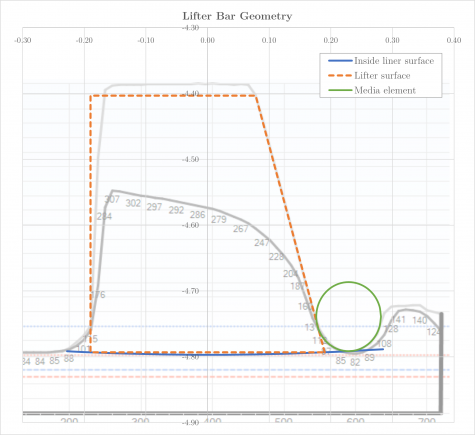
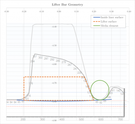
Modern mill interior laser scanning devices and/or design drawings provide accurate parametric maps of lifter bar geometry, which may be used to quantify the lifter height ([math]\displaystyle{ h }[/math]), lifter width ([math]\displaystyle{ 2y }[/math]) and lifter face angle ([math]\displaystyle{ \rho }[/math]) properties for media trajectory simulation.
Such scans and drawings may be carefully traced to determine the lifter dimensions, as demonstrated in Figures 5 and 6.
When tracing scans or drawings, the media element should be positioned at the lowest resting point in contact with both the shell liner and lifter bar.
An noted by Powell (1991), a media element moving down a lifter that encounters a lower face angle immediately falls away and is projected into free flight:
- The lifter height and face angle must therefore be chosen to represent the 'effective' geometry, where the tip of the lifter occurs at the first observed instance of the face angle decreasing
- This is particularly relevant for worn lifters, which tend to exhibit a lessening face angle due to the action of abrasive wear
- Figures 5 and 6 illustrate the selection of effective lifter dimensions with reducing face angle in mind
Excel
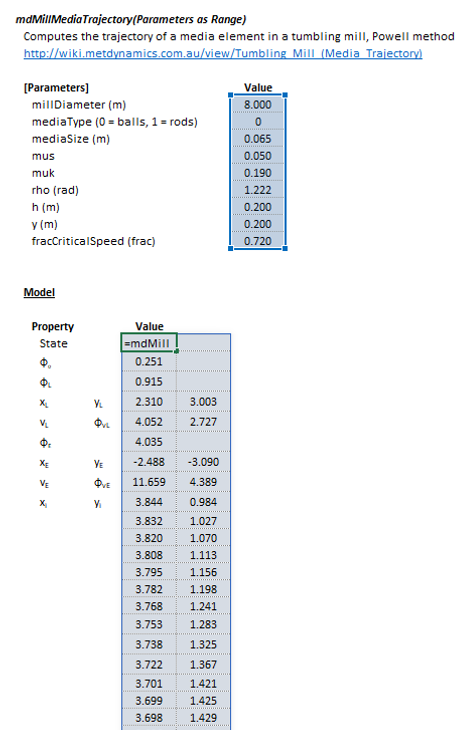
The tumbling mill media trajectory model may be invoked from the Excel formula bar with the following function call:
=mdMillPower_MillMediaTrajectory(Parameters as Range)
Invoking the function with no arguments will print Help text associated with the model, including a link to this page.
The Parameters array and model results are defined below in matrix notation, along with an example image showing the selection of the same arrays in the Excel interface:
and:
|
SysCAD
The media trajectory model is an optional calculation for tumbling mill units. If selected, the input and display parameters below are shown.
| Tag (Long/Short) | Input / Display | Description/Calculated Variables/Options |
|---|---|---|
| Requirements | ||
| MillDiameter | Input/Display | Diameter of the mill (inside liners). |
| FracCS | Input/Display | Fraction critical speed of the mill. |
| MediaType | Ball/Rod | Type of media element, balls or rods. |
| MediaSize | Display | Diameter of the media element. |
| mus | Input | Coefficient of static friction. |
| muk | Input | Coefficient of kinematic friction. |
| rho | Input | Lifter face angle, angle between the face surface and the base of the lifter bar. |
| h | Input | Height of the lifter bar. |
| 2y | Input | Width of the lifter bar. |
| Results | ||
| Point Of Equilibrium | ||
| PositionAngle | Display | Angular position of the point of equilibrium. |
| Leaves Lifter | ||
| PositionAngle | Display | Angular position of the point where the media element leaves the lifter. |
| X | Display | Cartesian x coordinate of the point where the media element leaves the lifter. |
| Y | Display | Cartesian y coordinate of the point where the media element leaves the lifter. |
| Velocity | Display | Velocity of the media element at the point where it leaves the lifter. |
| VelocityAngle | Display | Angular direction of the velocity of the media element at the point where it leaves the lifter. |
| Impacts Shell | ||
| PositionAngle | Display | Angular position of the point where the media element impacts the mill shell. |
| X | Display | Cartesian x coordinate of the point where the media element impacts the mill shell. |
| Y | Display | Cartesian y coordinate of the point where the media element impacts the mill shell. |
| Velocity | Display | Velocity of the media element at the point where it impacts the mill shell. |
| VelocityAngle | Display | Angular direction of the velocity of the media element at the point where it impacts the mill shell. |
| State | Display | Text description of the motion of the media element. Possible values are:
|
| Trajectory | ||
| TrajectoryData | Copies the full set of trajectory coordinates to the Windows clipboard in CSV format. | |
| Point, X, Y | Display | X and Y coordinates of the media element trajectory, from the point of equilibrium to point of impact with the mill shell. |
See also
References
- ↑ 1.0 1.1 1.2 1.3 1.4 Powell, M.S., 1991. The effect of liner design on the motion of the outer grinding elements in a rotary mill. International Journal of Mineral Processing, 31(3-4), pp.163-193.
- ↑ Powell, M.S., 1988. The effect of liner design upon charge motion in a rotary mill (Master's thesis, University of Cape Town).
