Tumbling Mill (Power, Morrell Continuum): Difference between revisions
Scott Munro (talk | contribs) m (1 revision imported) |
md>Scott.Munro mNo edit summary |
||
| Line 27: | Line 27: | ||
The net power imparted to the charge in the cylindrical section of the mill was analytically derived as: | The net power imparted to the charge in the cylindrical section of the mill was analytically derived as: | ||
:<math>P_{\rm t} = \frac{\pi g L N_{\rm m} r_{\rm m}}{3 \left (r_{\rm m} - | :<math>P_{\rm t} = \frac{\pi g L N_{\rm m} r_{\rm m}}{3 \left (r_{\rm m} - zr_{\rm i} \right )} \left [ 2r_{\rm m}^3 - 3zr_{\rm m}^2 + r_{\rm i}^3 \left (3z - 2 \right ) \right ] \times \big [ \rho_{\rm c} \left ( \sin \theta_{\rm S} - \sin \theta_{\rm T} \right ) + \rho_{\rm p} \left ( \sin \theta_{\rm T} - \sin \theta_{\rm TO} \big ) \right ] + L \rho_{\rm c} \left ( \frac{N_{\rm m}r_{\rm m} \pi}{\left ( r_{\rm m} - zr_{\rm i} \right)} \right ) \left [ \left( r_{\rm m} - zr_{\rm i} \right )^4 - r_{\rm i}^4 \left (z - 1 \right )^4 \right ] </math> | ||
and for the cone end section: | and for the cone end section: | ||
:<math>P_{\rm c} = \frac{\pi L_{\rm d} g N_{\rm m}}{3(r_{\rm m} - r_{\rm t})} \bigg \{ \left ( r_{\rm m}^4 - 4r_{\rm m} | :<math>P_{\rm c} = \frac{\pi L_{\rm d} g N_{\rm m}}{3(r_{\rm m} - r_{\rm t})} \bigg \{ \left ( r_{\rm m}^4 - 4r_{\rm m}r_{\rm i}^3 + 3r_{\rm i}^4 \right ) \big[ \rho_{\rm c} \left ( \sin \theta_{\rm S} - \sin \theta_{\rm T} \right ) + \rho_{\rm p} \left ( \sin \theta_{\rm T} - \sin \theta_{\rm TO} \right ) \big] \bigg \} + \frac{2 \pi^3 N_{\rm m}^3 L_{\rm d} \rho_{\rm c}}{5(r_{\rm m} - r_{\rm t})} \big ( r_{\rm m}^5 - 5r_{\rm m}r_{\rm i}^4 + 4r_{\rm i}^5 \big )</math> | ||
where: | where: | ||
| Line 44: | Line 44: | ||
* <math>r_{\rm m}</math> is the mill radius inside liners (m) | * <math>r_{\rm m}</math> is the mill radius inside liners (m) | ||
* <math>r_{\rm t}</math> is the trunnion radius inside liners (m) | * <math>r_{\rm t}</math> is the trunnion radius inside liners (m) | ||
* <math> | * <math>r_{\rm i}</math> is the inner charge surface radius (m) | ||
* <math>\theta_{\rm S}</math> is the angle of the charge shoulder (radians) | * <math>\theta_{\rm S}</math> is the angle of the charge shoulder (radians) | ||
* <math>\theta_{\rm T}</math> is the angle of the charge toe (radians) | * <math>\theta_{\rm T}</math> is the angle of the charge toe (radians) | ||
| Line 71: | Line 71: | ||
=== Charge position === | === Charge position === | ||
The charge motion power equations require the position of the charge shoulder (<math>\theta_{\rm S}</math>), charge toe (<math>\theta_{\rm T}</math>), slurry pool level (<math>\theta_{\rm TO}</math>, for overflow discharge mills) and the inner charge surface radius (<math> | The charge motion power equations require the position of the charge shoulder (<math>\theta_{\rm S}</math>), charge toe (<math>\theta_{\rm T}</math>), slurry pool level (<math>\theta_{\rm TO}</math>, for overflow discharge mills) and the inner charge surface radius (<math>r_{\rm i}</math>), in addition to mill dimensions and charge composition. | ||
Morrell developed the following series of relations to estimate the charge geometry.{{Morrell (1996a)}} | Morrell developed the following series of relations to estimate the charge geometry.{{Morrell (1996a)}} | ||
| Line 103: | Line 103: | ||
where <math>r_{\rm t}</math> (m) is the radius of the trunnion. | where <math>r_{\rm t}</math> (m) is the radius of the trunnion. | ||
The inner '''charge surface radius''', <math> | The inner '''charge surface radius''', <math>r_{\rm i}</math> (m), is: | ||
:<math> | :<math>r_{\rm i} = r_{\rm m} \left ( 1 - \frac{2 \pi \beta J_{\rm t}}{2 \pi + \theta_{\rm S} - \theta_{\rm T}} \right )^{0.5}</math> | ||
where the fraction of total charge in the active region, <math>\beta</math> (frac), is: | where the fraction of total charge in the active region, <math>\beta</math> (frac), is: | ||
| Line 193: | Line 193: | ||
\theta_{\rm T} \text{ (rad)}\\ | \theta_{\rm T} \text{ (rad)}\\ | ||
\theta_{\rm TO} \text{ (rad)}\\ | \theta_{\rm TO} \text{ (rad)}\\ | ||
r_{\rm i}\text{ (m)}\\ | |||
\end{bmatrix}\;\;\;\;\;\; | \end{bmatrix}\;\;\;\;\;\; | ||
</math> | </math> | ||
Revision as of 13:25, 14 May 2023
Description
This article describes the Morrell Continuum (Morrell C) method for estimating the power draw of a tumbling mill.[1]
The Morrell C model is a theoretical approach based on the dynamics of the grinding charge. By making simplifying assumptions about the charge shape, composition and position, Morrell developed analytical solutions to equations describing the the rate at which potential and kinetic energy is imparted to the charge during mill rotation.
Model theory
Morrell's Continuum approach expresses power input to the motor of a tumbling mill as:[1]
where is a lumped calibration parameter accounting for power losses, found to be a value of 1.26 for industrial mills.
Sub-components of the gross power equation are described below.
Charge motion power
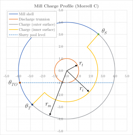
To determine the charge motion power, Morrell adopted the simplified continuum charge shape shown in Figure 1.
Power draw is then developed from a consideration of the rate at which potential and kinetic energy is transferred to the charge and the slurry pool (if present).
The net power imparted to the charge in the cylindrical section of the mill was analytically derived as:
and for the cone end section:
where:
- is power draw of the cylindrical section of the mill (kW)
- is power draw of the two cone ends of the mill (kW)
- is length of the cylindrical section (belly) of the mill inside liners (m)
- is length of the cone end (m)
- is acceleration due to gravity (m/s2)
- is the rotational rate of the mill (rev/s)
- is the density of the total charge (t/m3)
- is the density of discharge pulp (t/m3)
- is the mill radius inside liners (m)
- is the trunnion radius inside liners (m)
- is the inner charge surface radius (m)
- is the angle of the charge shoulder (radians)
- is the angle of the charge toe (radians)
- is the angle of the slurry pool surface at the toe (radians)
and all angles are unit circle positive.
The total charge motion power is the sum of the net power imparted to the charge in the cylindrical and cone sections, i.e.
The length of the cone end, (m), is:
where is the cone angle, measured as the angular displacement of the cone surface from the vertical direction (rad).
The parameter is an empirical term that relates the rotational rate of particles at radial positions within the charge to the rotational rate of the mill, and is defined as:
where is the volumetric fraction of the mill occupied by balls and coarse rock (including void space and interstitial slurry) (v/v).
The remaining parameters of the charge motion power equations are described below.
Charge position
The charge motion power equations require the position of the charge shoulder (), charge toe (), slurry pool level (, for overflow discharge mills) and the inner charge surface radius (), in addition to mill dimensions and charge composition.
Morrell developed the following series of relations to estimate the charge geometry.[1]
The position of the toe of the charge, (rad), is defined as:
where (frac) is the theoretical fraction critical speed, and the fraction of critical speed at which centrifuging actually occurs, (frac), is:
The position of the shoulder of the charge, (rad), is:
The position of the slurry pool level, (rad), is:
where (m) is the radius of the trunnion.
The inner charge surface radius, (m), is:
where the fraction of total charge in the active region, (frac), is:
The time taken to travel between the toe and shoulder of the charge during one revolution, (s), is:
where the mean rotational rate, (rev/s), is:
The time taken to travel between the shoulder and toe of the charge in free flight during one revolution, (s), is:
where the mean radial position (m), is:
Charge density
The apparent density of the charge, , including balls, coarse rocks, voids and slurry, is:[1]
where:
- is the density of ore (t/m3)
- is volumetric fraction of interstitial void space in the charge, typically 0.4 (v/v)
- is the volumetric fraction of interstitial grinding media voidage occupied by slurry (v/v),
- is the volume fraction of solids in the mill discharge (v/v)
- is the volumetric fraction of the mill occupied by balls (including voids) (v/v)
No-load power
No-load power is defined as:
where is mill diameter inside liners (m)
Additional notes
The Morrell C model is only applicable to grate discharge mills that do not exhibit a slurry pool, i.e. .
For overflow discharge mills, the slurry pool component is accounted for by the term, which assumes overflow at the exact height of the trunnion lip.
Excel
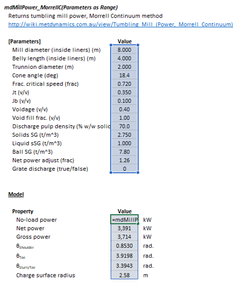
The Morrell Continuum mill power model may be invoked from the Excel formula bar with the following function call:
=mdMillPower_MorrellC(Parameters as Range)
Invoking the function with no arguments will print Help text associated with the model, including a link to this page.
The Parameters array and model results are defined below in matrix notation, along with an example image showing the selection of the same arrays in the Excel interface:
|
|
SysCAD
The Morrell Continuum power model is an optional calculation for tumbling mill units. If selected, the input and display parameters below are shown.
See also
References
- ↑ 1.0 1.1 1.2 1.3 Morrell, S., 1996. Power draw of wet tumbling mills and its relationship to charge dynamics. Pt. 1: a continuum approach to mathematical modelling of mill power draw. Transactions of the Institution of Mining and Metallurgy. Section C. Mineral Processing and Extractive Metallurgy, 105.


![{\displaystyle P_{\rm {t}}={\frac {\pi gLN_{\rm {m}}r_{\rm {m}}}{3\left(r_{\rm {m}}-zr_{\rm {i}}\right)}}\left[2r_{\rm {m}}^{3}-3zr_{\rm {m}}^{2}+r_{\rm {i}}^{3}\left(3z-2\right)\right]\times {\big [}\rho _{\rm {c}}\left(\sin \theta _{\rm {S}}-\sin \theta _{\rm {T}}\right)+\rho _{\rm {p}}\left(\sin \theta _{\rm {T}}-\sin \theta _{\rm {TO}}{\big )}\right]+L\rho _{\rm {c}}\left({\frac {N_{\rm {m}}r_{\rm {m}}\pi }{\left(r_{\rm {m}}-zr_{\rm {i}}\right)}}\right)\left[\left(r_{\rm {m}}-zr_{\rm {i}}\right)^{4}-r_{\rm {i}}^{4}\left(z-1\right)^{4}\right]}](https://wikimedia.org/api/rest_v1/media/math/render/svg/8ebd392ddc10b38f0a978ae5a860ccdb2882139f)
![{\displaystyle P_{\rm {c}}={\frac {\pi L_{\rm {d}}gN_{\rm {m}}}{3(r_{\rm {m}}-r_{\rm {t}})}}{\bigg \{}\left(r_{\rm {m}}^{4}-4r_{\rm {m}}r_{\rm {i}}^{3}+3r_{\rm {i}}^{4}\right){\big [}\rho _{\rm {c}}\left(\sin \theta _{\rm {S}}-\sin \theta _{\rm {T}}\right)+\rho _{\rm {p}}\left(\sin \theta _{\rm {T}}-\sin \theta _{\rm {TO}}\right){\big ]}{\bigg \}}+{\frac {2\pi ^{3}N_{\rm {m}}^{3}L_{\rm {d}}\rho _{\rm {c}}}{5(r_{\rm {m}}-r_{\rm {t}})}}{\big (}r_{\rm {m}}^{5}-5r_{\rm {m}}r_{\rm {i}}^{4}+4r_{\rm {i}}^{5}{\big )}}](https://wikimedia.org/api/rest_v1/media/math/render/svg/1f6431d668ba04e62237cdfb20257fa2edc605fa)


![{\displaystyle \theta _{\rm {S}}={\frac {\pi }{2}}-\left(\theta _{\rm {T}}-{\frac {\pi }{2}}\right){\big [}\left(0.336+0.1041\phi \right)+\left(1.54-2.5673\phi \right)J_{\rm {t}}{\big ]}}](https://wikimedia.org/api/rest_v1/media/math/render/svg/f40057812484b5eacef0d4cc2561789aee151b20)


![{\displaystyle {\bar {r}}={\frac {r_{\rm {m}}}{2}}\left[1+\left(1-{\frac {2\pi J_{\rm {t}}}{2\pi +\theta _{\rm {S}}-\theta _{\rm {T}}}}\right)^{0.5}\right]}](https://wikimedia.org/api/rest_v1/media/math/render/svg/f2864bb1dd69819f55c3f8ec93aef9c0cbd36edc)


![{\displaystyle {\text{No-load power}}=1.68D^{2.05}\left[\phi (0.667L_{\rm {d}}+L\right]^{0.82}}](https://wikimedia.org/api/rest_v1/media/math/render/svg/e93f54c8105dbecc440d9501e5c89f063bae0d6c)


